Cycloidal Speed Reducer [2025]
Summary and Key Details
Developed a compact 15:1 speed reducer, designed to lift 2 kilograms at a 0.2-meter distance from its pivot
Conducted SOLIDWORKS motion studies to validate the function of the cycloidal drive mechanism
Iteratively developed the design by testing pin layouts, shaft configurations, and exploring strategies to minimize losses in vibration and friction
Note: Details on testing, efficiency, and load calculations will be added soon.
Motivation
I wanted to take on a design project that challenged my current skills. With the recent wave of humanoid robotics, I found myself diving into the field, reading and learning more about its intricacies. Along the way, I stumbled upon cycloidal drives and was captivated by their mechanics and motion.
Furthermore, I thought that it would be the perfect first step in eventually re-creating my first ever personal project - The Mimicking Robotic Arm.
Armed with a long-term goal and how this project would fit into the picture, I was eager to get to work.
Background - What is a Cycloidal Drive?
When I began this project, I had no idea what a cycloidal drive was, so it’s only fair for me to give a quick run-down.
A cycloidal drive is type of speed reducer, designed to lower rotational speed while increasing torque. It achieves this by leveraging an eccentric shaft, which is connected to the input. This shaft rotates a cycloidal disk.
The cycloidal disk makes contact with fixed rollers which results in a distinct wobbling rotation. The output is generated by placing pins through holes in the cycloidal disk.
First Design Concept
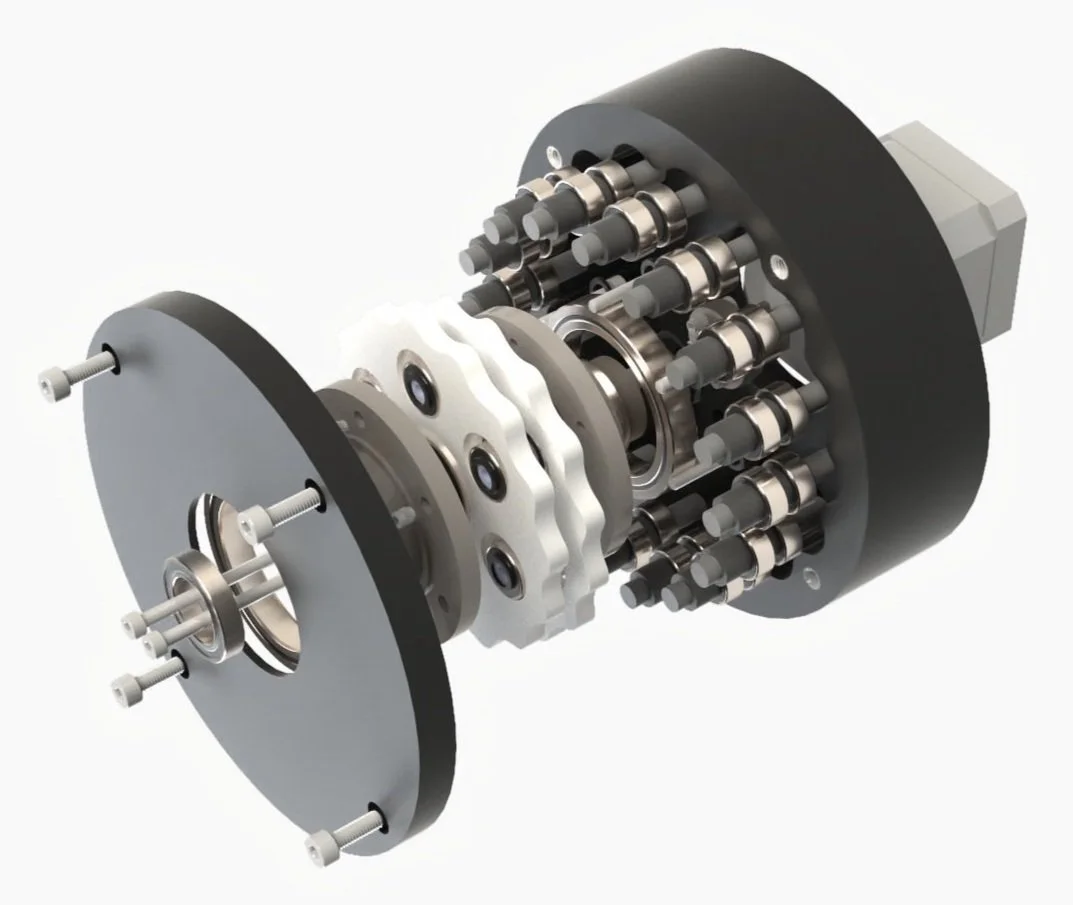
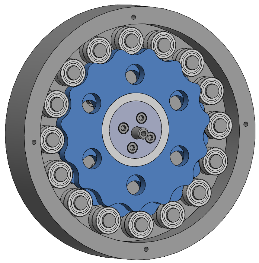
Using the calculations in the Appendix which led to a speed reduction choice of 15:1, I began by designing the pin disk enclosure. The first major design choice of mine was to use bearings instead of fixed pins to reduce friction and losses. To obtain a 15:1 reduction, the pin disk enclosure has 16 pins.
The design utilizes two cycloidal disks instead of one. This decision was based on research indicating that the eccentric nature of a single disk causes vibrations and losses. By offsetting the second disk by 180 degrees, the vibrations are balanced, reducing the impact.
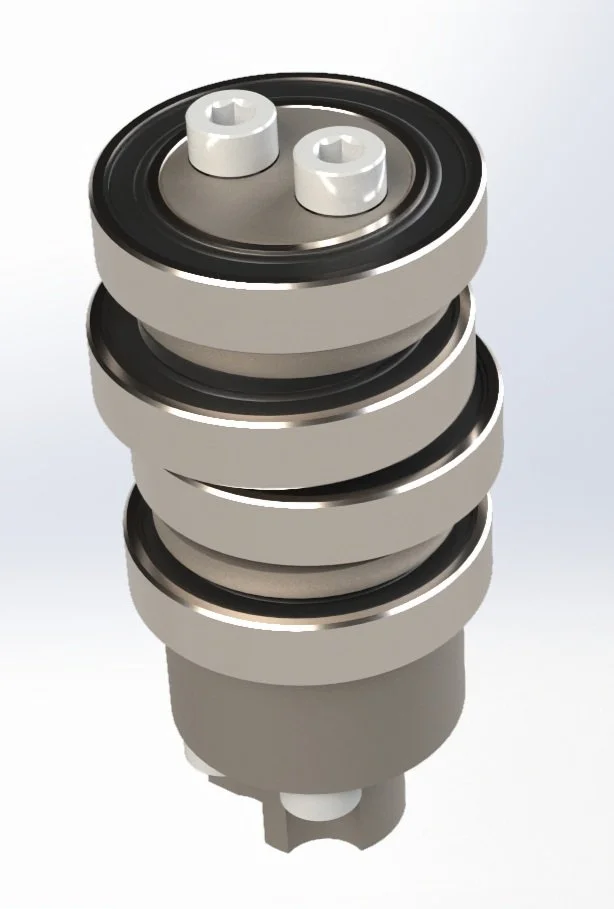
The disk surrounding the central shaft serves as a mounting hub between the motor and the CAM shaft. The CAM shaft components I designed attach to the four holes on the hub, transferring the motor's rotation to the cycloidal disks. The CAM shaft can be seen in the image below, consisting of 2 eccentric disks for each cycloidal disk.
I began by designing the pin disk enclosure based on the specified dimensions, opting for bearings instead of fixed pins to reduce friction and losses. The design features 16 pins for a 15:1 reduction ratio.
The design utilizes two cycloidal disks instead of one. This decision was based on research indicating that the eccentric nature of a single disk causes vibrations and losses. By offsetting the second disk by 180 degrees, the vibrations are balanced, reducing the impact.
Completed First Design and Animations
The fully assembled first design is pictured below.
Additionally, I ran motion studies in SOLIDWORKS using the Motion Analysis Simulation tool. I did this by specifying contacts between the roller pin bearings, cycloidal disks, and eccentric shafts. This simulation validated the speed reduction function.
Iteration 2: Design Improvements
After completing the initial design, I took some time to reflect on its flaws, explore potential improvements, and conduct additional research. During this period, I finalized a few key decisions for the final design.
Motor Mounting Approach
In the first iteration, the NEMA 17 motor was mounted directly through the pin disk enclosure. However, I realized that removing the motor would require disassembling the entire cycloidal drive. For the second design, I incorporated heat-set inserts on the back for accessibility.
Output Shaft
I observed that the previous pin disk design lacked balance, as the pins were inserted into the drive without support on the other ends. Through research on cycloidal drives, I identified an approach where the output shaft passes through the cycloidal disks, providing two points of contact—one at the top and another at the bottom of the enclosure. This approach greatly improves stability and reinforces the overall design.
Spacing Components and Bearings
An oversight I realized in my initial design was that the cycloidal drive and pin disk bearings were making direct contact. To address this, I added spacers between them to reduce friction. While this increased the design's complexity, the improvement in performance makes it worthwhile.
Final Design - Assembly
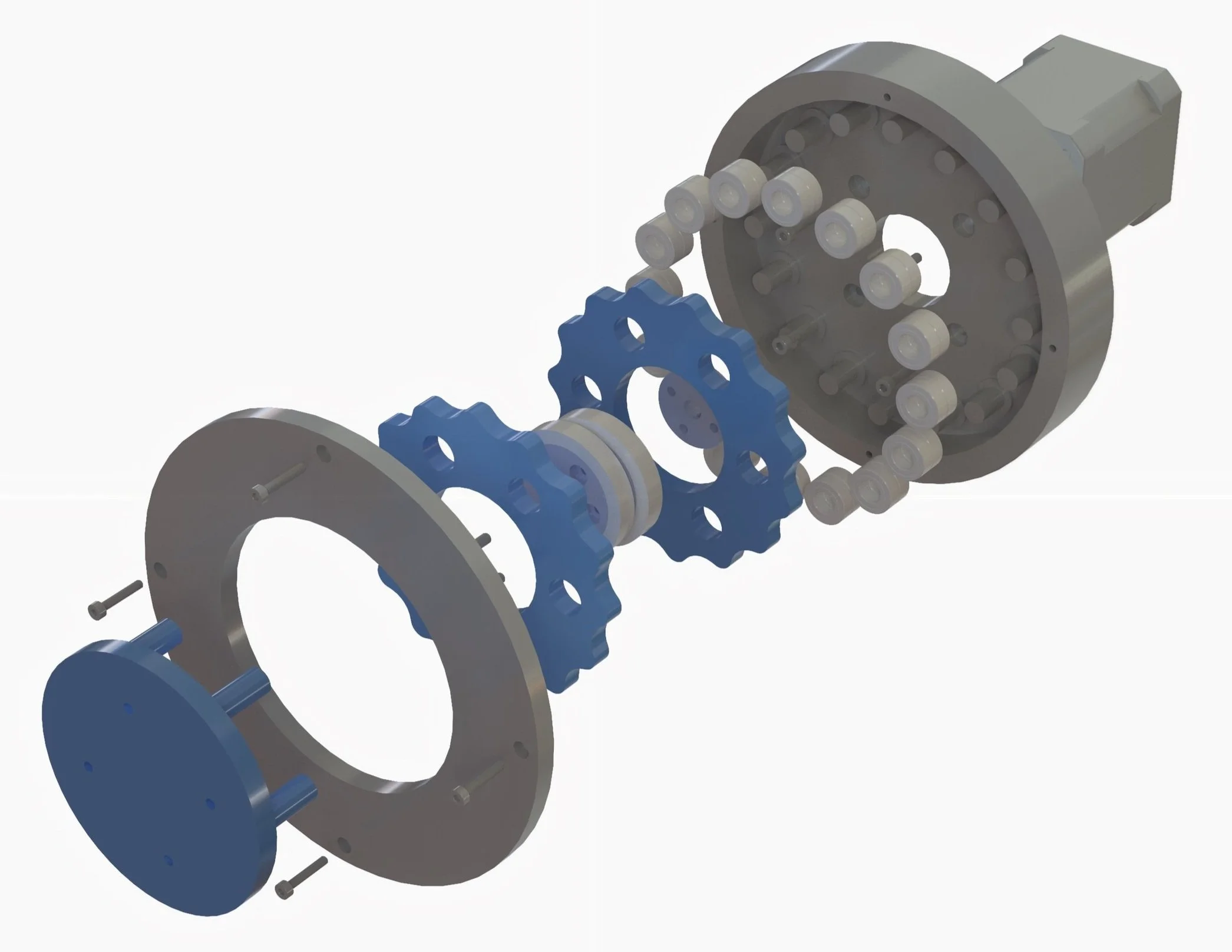
The key details of the final design include:
16 fixed pins enabling a 15:1 speed reduction
2 offset cycloidal disks designed to minimize vibrations
Bearings between the disks, output shaft, and pins to reduce friction
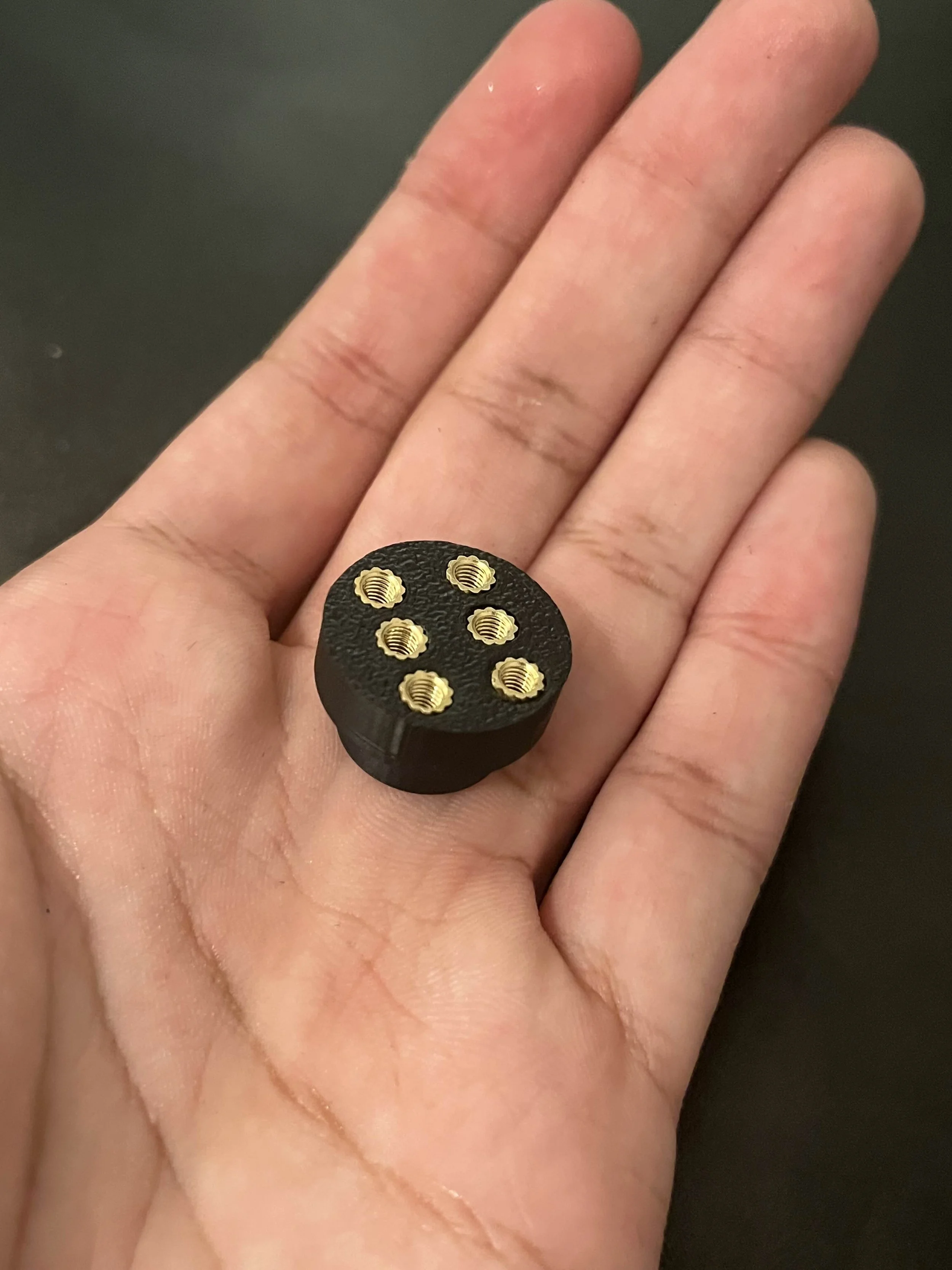
An eccentric shaft consisting of 4 main parts secured with heat-set inserts
A mounting hub connecting the motor to the eccentric shaft.
An output shaft made up of 2 plates and 6 pins
Final Design - Output and Eccentric Shafts
Final Design Motion Studies
To validate the function of the cycloidal drive, I utilized motion studies in SOLIDWORKS. The results are shown below.
Product Assembly
With the assembly being very involved, I thought the best way to take you through it would be through a series of photos.
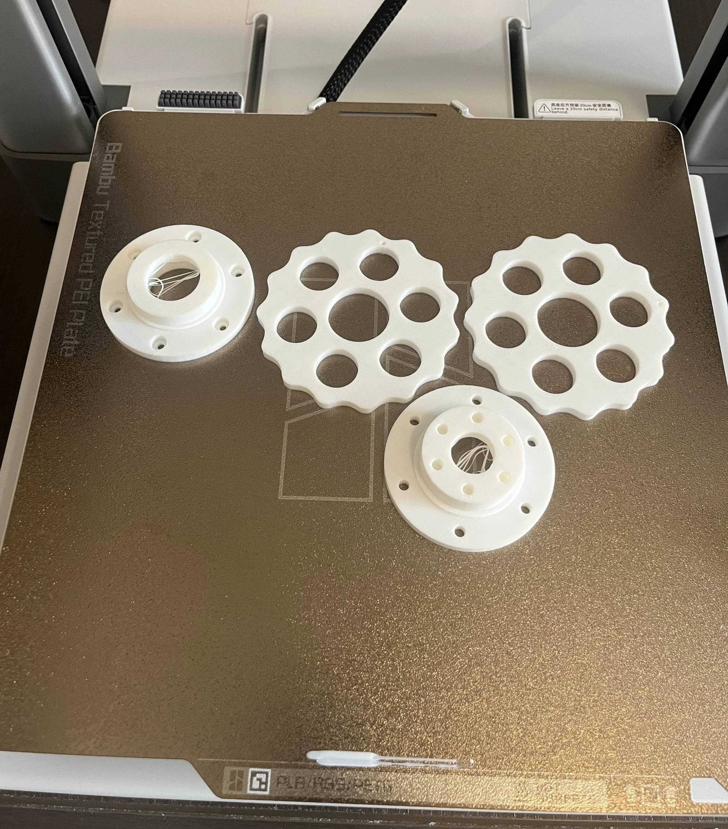
3D Printed Parts
Fixed Pin Disk Assembly
Eccentric Shaft Assembly
Output Shaft Assembly
Completed Product
Appendix - Speed Reduction Calculations
To establish a guideline for the required speed reduction, I determined that the robotic arm should be capable of holding a 2-kilogram mass 20 centimeters from the pivot point.
A NEMA 17 stepper motor was chosen to drive the cycloidal drive due to its precision, reliability, and ease of control. The chosen motor had a holding torque of 0.54 Nm. Using estimations from research, the continuous torque was taken to be 50% of the holding torque.
The cycloidal drive would clearly not be an ideal system. However, this provides a metric to gauge efficiency.
Appendix - Cycloidal Disk Design
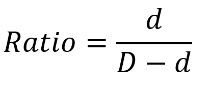
The speed reduction depends on the number of fixed pins (D), and the number of rings on the cycloidal disk (d), and is given by:
To minimize materials and cost, 16 pins and 15 rings on the disk were chosen to achieve a speed reduction ratio of 15:1.
To produce the cycloidal disk profile, while researching, I came across parametric equations that can be used in SOLIDWORKS to create the sketch. The dimensions I chose were based on trial and error for my desired form factor, as well as designing around hardware I already owned such as certain bearings.
Roller (Fixed Pin) Radius: 7 cm
Disk Radius: 50 cm
Eccentricity: 1.5 cm
Appendix - Motor Control
The Cycloidal Drive was powered by a DC power supply.
An Arduino controlled the NEMA 17 motor, paired with an A4988 Stepper Motor Driver Module.
Relevant resources are available [here].
