Remote-Controlled Light Switch [2023]
Summary and Key Details
Designed a Bluetooth-controlled light switch with a custom GUI as a home automation solution
Integrated the hardware of the light switch panel into the product assembly for ease of installation
Programmed the GUI in Processing IDE to send commands to an Arduino via a Bluetooth module
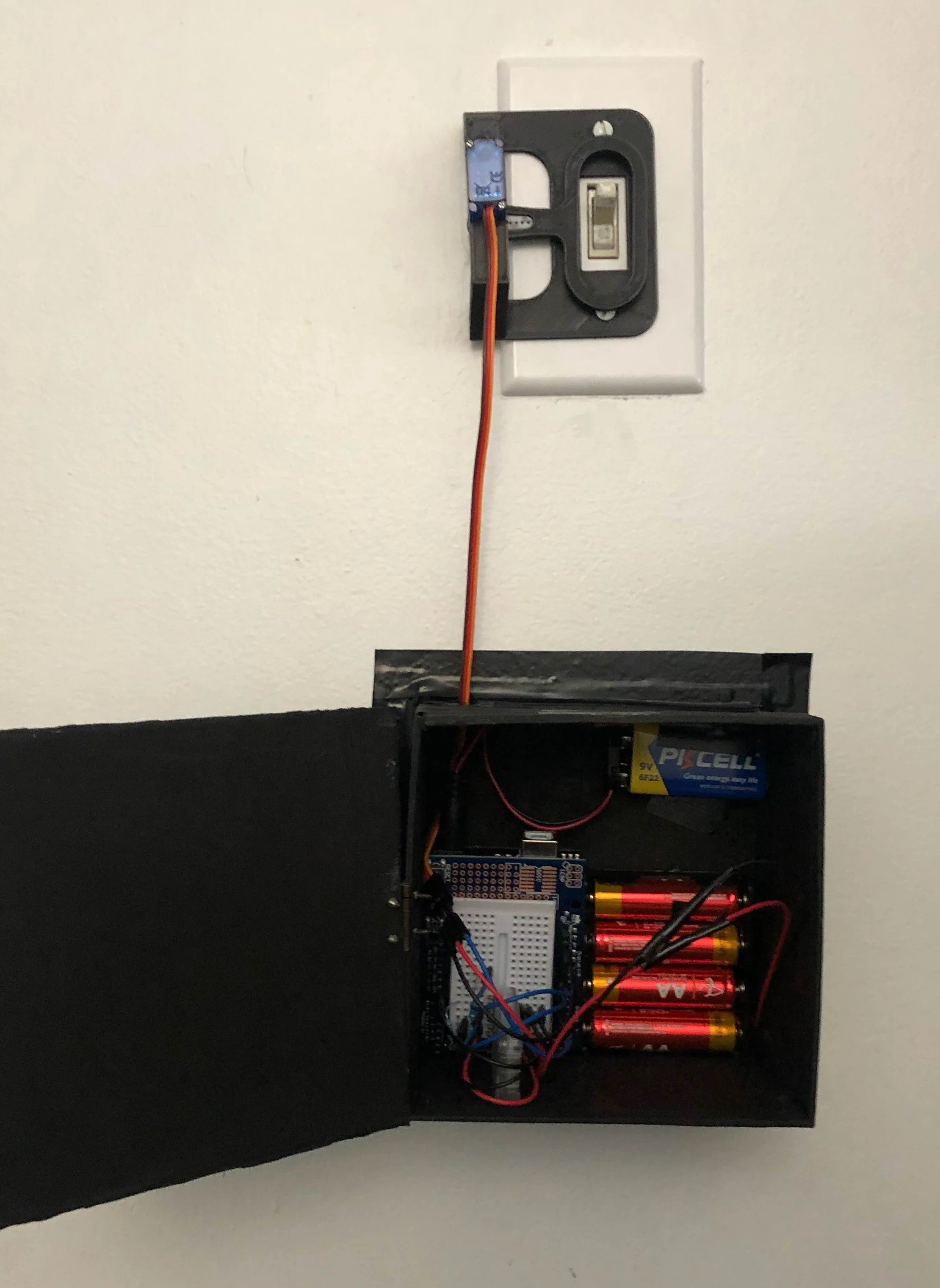
Final Product
Component List
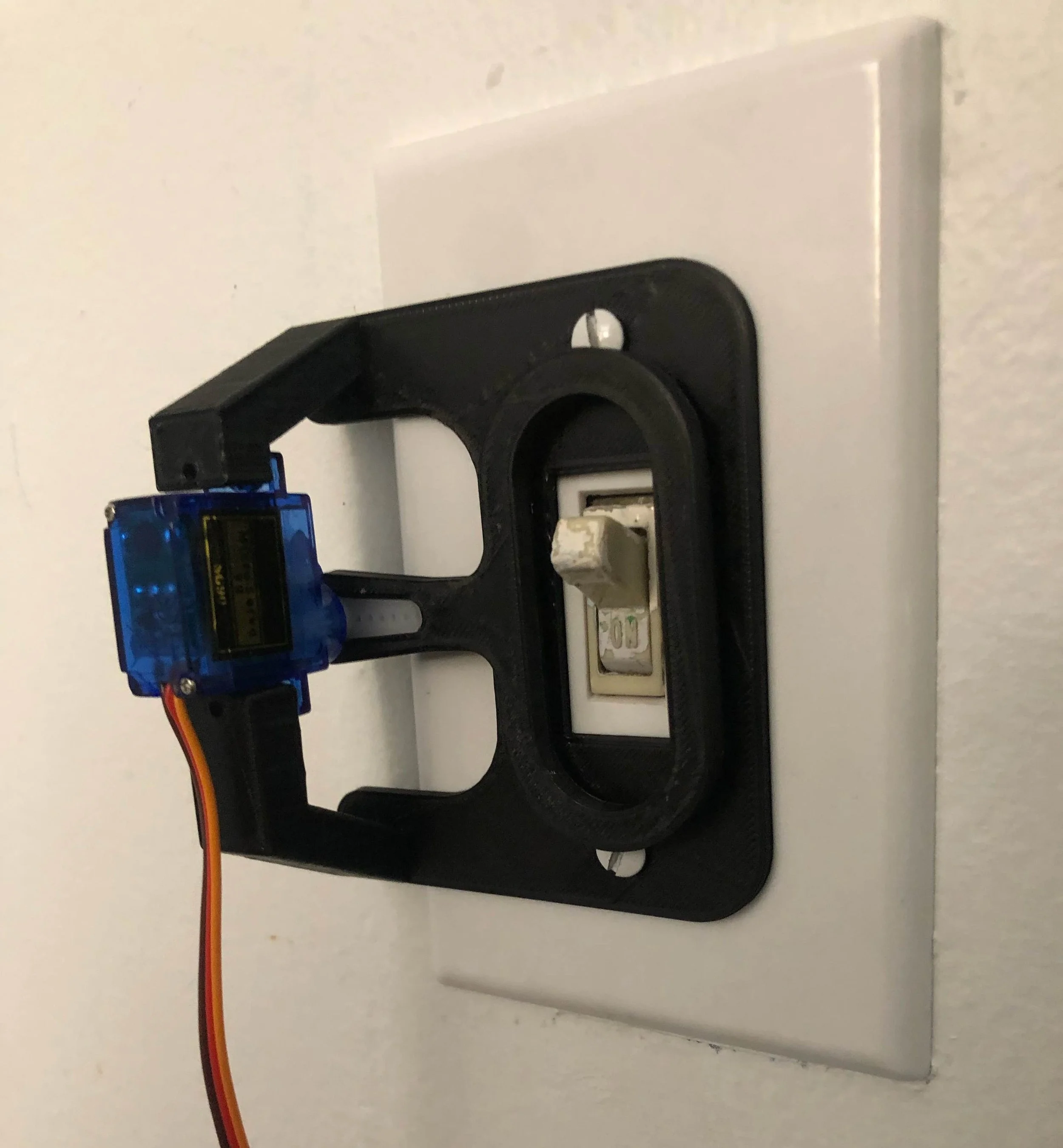
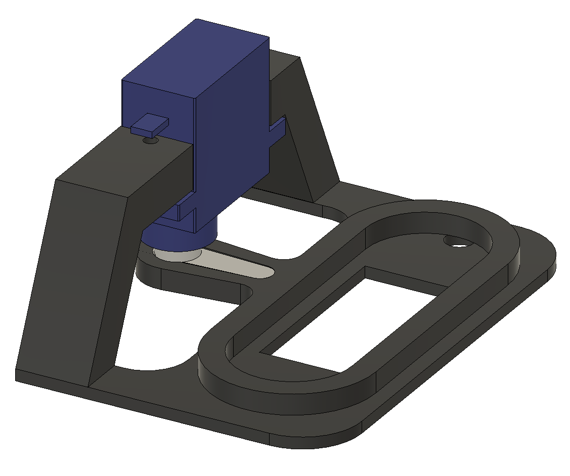
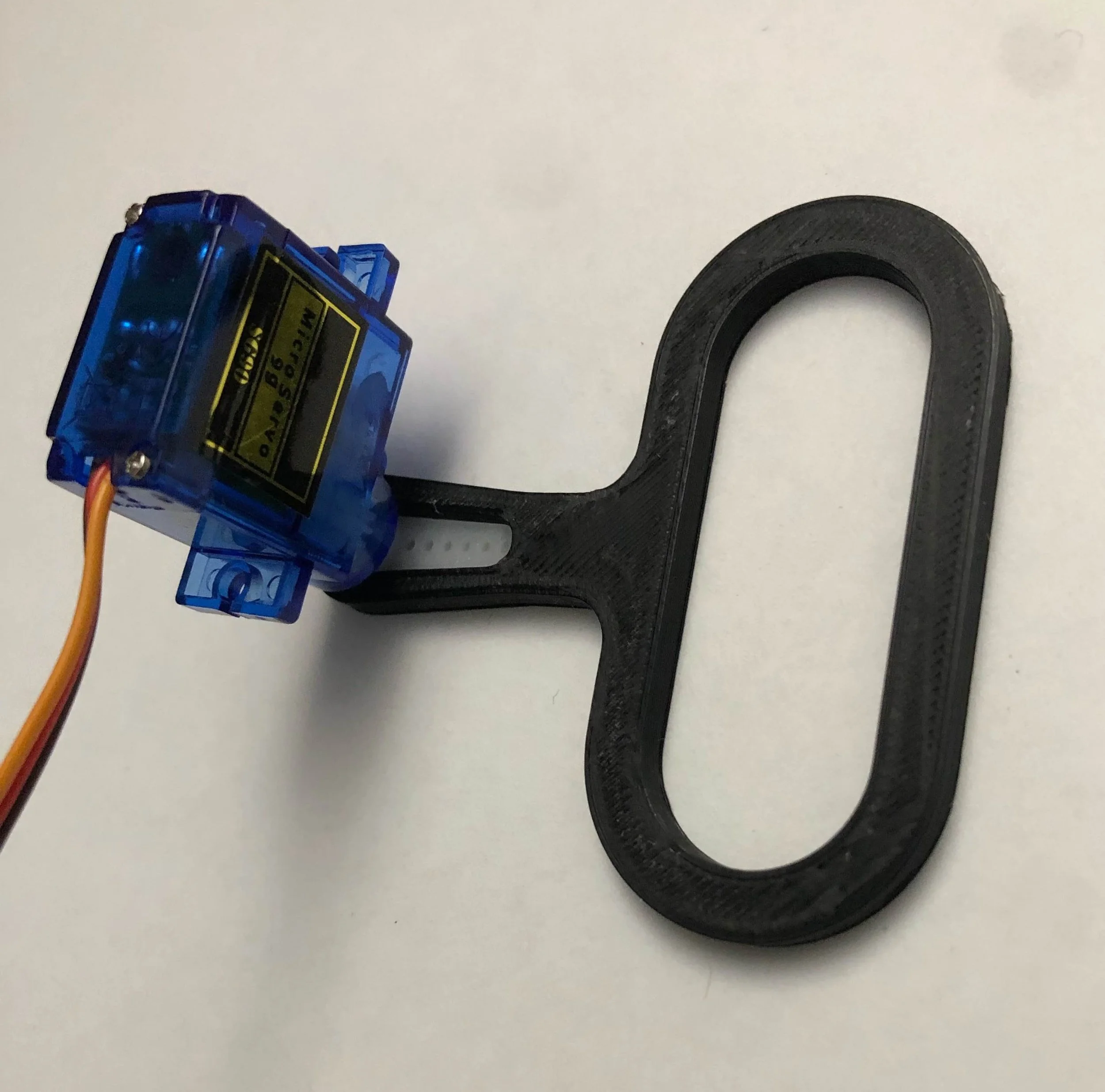
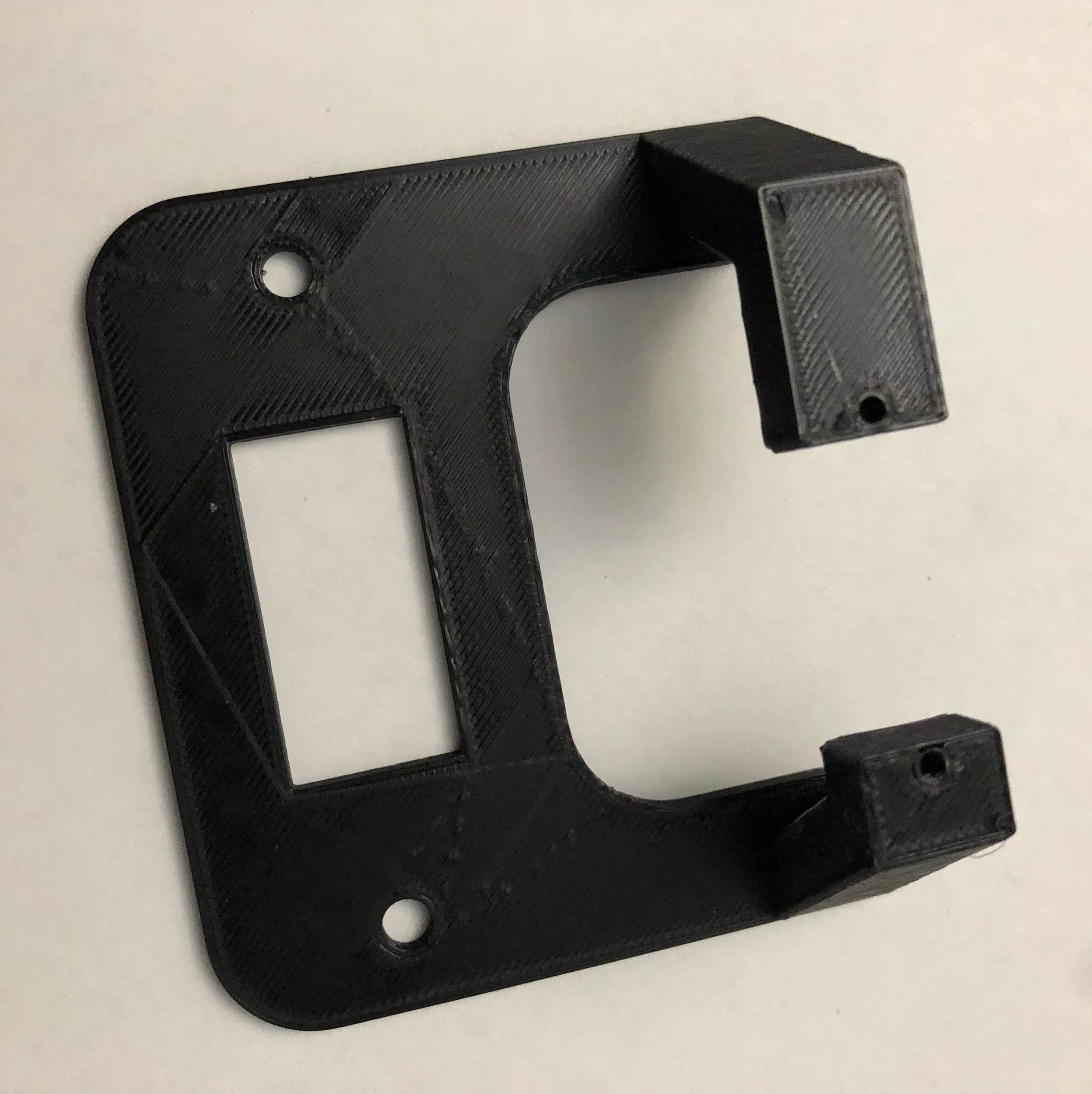
Servo Motor Mounting Bracket (3D Printed)
Servo Motor Arm (3D printed)
SG90 Servo Motor
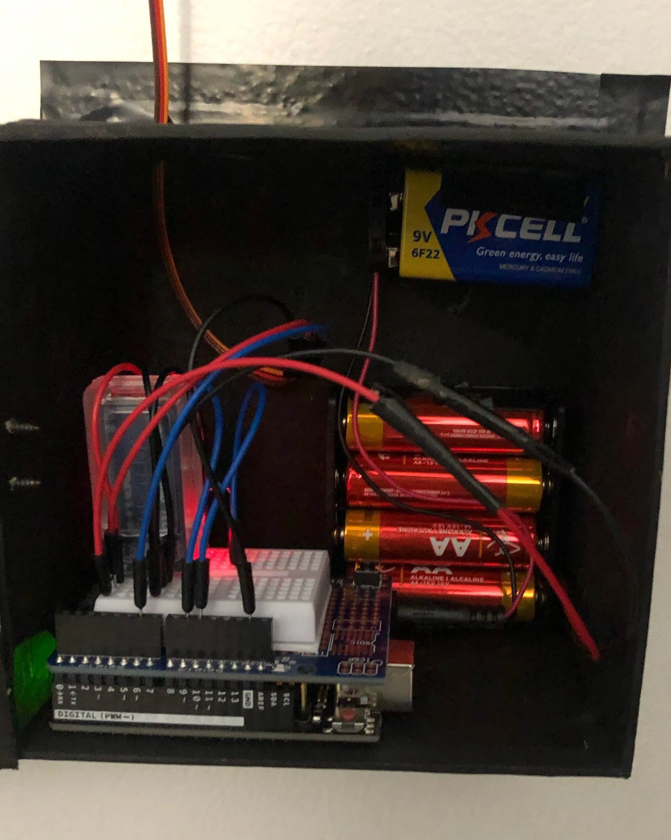
Arduino and HC-05 Wireless Bluetooth Module
9V Battery to Power Arduino
6V 4xAA Battery Pack for Circuit Components
Electronics Enclosure (Very make-shift…)
Project Origin
This was the first project I ever worked on using CAD. When trying to figure out what I wanted to make, I thought to myself “what could I use”? In the mix of this all I was interested in the idea of home automation, and thought that it would be fun to be able to control my room light from anywhere.
This project would also save the hassle of my brother always turning my room light on when I wanted it off without me having to get up, so that was a big win.
Initial Requirements
When starting this project, I knew there were two functional requirements of the device:
The light switch device must be wireless
The light switch must still be able to be controlled manually
Since I was still living at home at this time, the second point was important to not upset my parents…
Product Ideation and Prototyping
After some brain storming, and research into other similar projects, I decided my approach was going to be a motor mounted onto the light switch, with an arm that flicked the light switch. I started the prototyping process by creating cardboard cut outs for the arm.
After some testing and refining the geometry to fit with my light switch, I went to design it in Fusion 360. I decided to integrate the screws in the light switch in order to avoid additional hardware. The design and 3D printed parts are below

Electronics and Software
In order to control the light switch, I decided that a GUI would be the most intuitive for any user, and the most cost-effective for me while I was budget constrained. Had I been able to allocate more resources, I would have created a secondary Bluetooth device to act as the controller for the light switch.
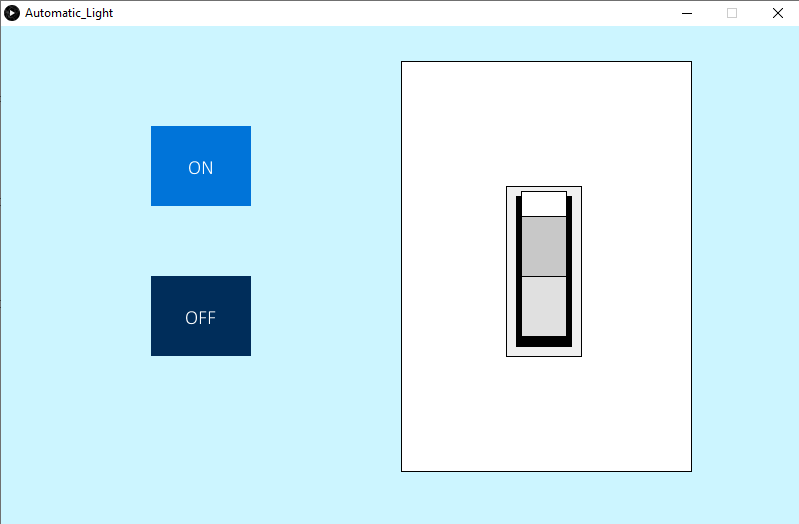
The GUI I designed consisted of simple “ON” and “OFF” buttons, as well as a graphic indicating the current status of the light.
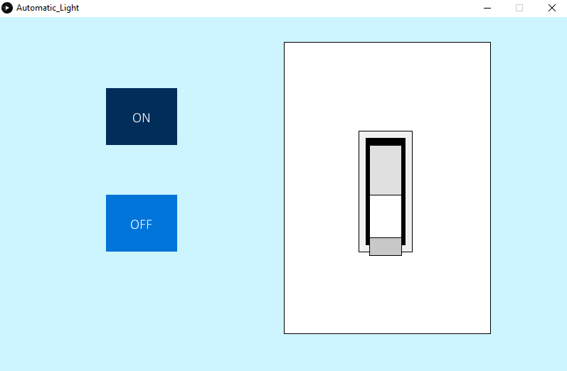
The GUI was built in the Processing IDE. The HC-05 Bluetooth module acted as the communication bridge between the Processing GUI and the Arduino. The Processing program establishes a serial connection with it, transmitting commands based on the button presses in the GUI.
Receiving
"ON"triggers the Arduino to activate a motor that flicks the light switch to the "on" position.
Receiving
"OFF"reverses the motor to switch the light off
Below is a video of the GUI interaction being tested, as well as a video of the final product.